Design Explorer Case Study 1
Objectives
In this example, we will replicate the diagram below:
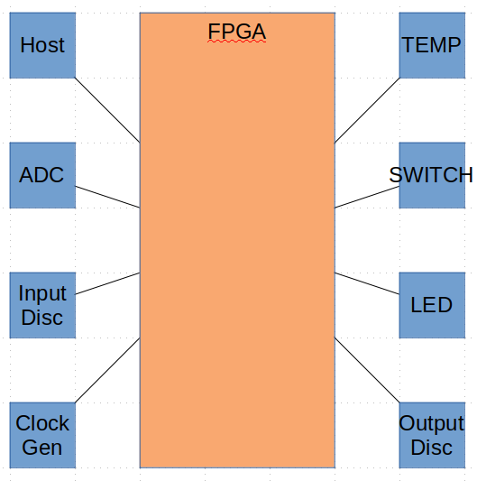
What we know:
- The system is composed of a single CCA
- There is an FPGA on the CCA
- The FPGA communicates with four devices
- We were given a set of requirements
Strategy
- Generate HW library
- Generate System
- Add components
- Create CCA
- Define interfaces on FPGA
- Add connections
- Decompose Requirements
- Architect FPGA
Generate HW Library
We have seven devices in our system and we were given which parts will be used:
| Device | Manufacturer | Part Number |
|---|---|---|
| ADC | Analog Devices | AD4110-1 |
| Temp Sensor | Analog Devices | LTC2986 |
| LED | Lite On | LTA-1000G |
| Host | Texas Instruments | OMAP-L137 |
| Discretes | N/A | N/A |
| Clock Gen | IDT | MK2771-16 |
| FPGA | Intel | MAX 10 |
Hardware Library Directory Structure
We will create a hardware library with the following format:
hw_lib
|
+-- adc
|   |
|   +-- analog_devices
|       |
|       +-- ad4110_1
|
+-- temp_sensor
|   |
|   +-- analog_devices
|       |
|       +-- ltc2986
|
+-- led
|   |
|   +-- lite_on
|       |
|       +-- lta_1000g
|
+-- processors
|   |
|   +-- texas_instruments
|       |
|       +-- omap_l137
|
+-- clock
|   |
|   +-- idt
|       |
|       +-- mk2771_16
|
+-- generic
|   |
|   +-- dicretes
|
+-- fpga
    |
    +-- intel
        |
        +-- max10
            |
            +-- max10M50
For each directory we will add a blank __init__.py file.
LED
We will start with the Lite On LED part LTA 1000G. First we make the directory.
mkdir -p hw_lib/led/lite_on/lta_1000g
The -p option on mkdir will create all the parent directories of lta_1000g. We will create the necessary __init__.py files at each level of the hierarchy.
hw_lib/__init__.py
from . import led
hw_lib/led/__init__.py
from . import lite_on
hw_lib/led/lite_on/__init__.py
from . import lta_1000g
hw_lib/led/lite_on/lta_1000g/__init__.py
We will split the modeling of the lta 1000g part into two files: interfaces and the part.
from . import interfaces
from .part import *
Seperating the interfaces into a seperate file will make it easier to re-use the interface.
Note
Need to really see if this is so. It might be better to combine the files into a single file and remove the extra level of hierarchy. Although having a directory to store everything for a part makes it easier to add features.
hw_lib/led/lite_on/lta_1000g/interfaces.py
We import design explorer:
import design_explorer as de
Looking at the data sheet we see only two interfaces: Anode and Cathode. The Anode is the end we would drive. The Cathode would be tied to ground.
First we create the interfaces:
import design_explorer as de

# Add the interface that we would drive to turn on and off the LEDs
oAnode = de.interface.create('Anode', source=False)

# This is the ground node
oCathode = de.interface.create('Cathode', source=True)
Then we add the ports to the interfaces:
import design_explorer as de

# Add the interface that we would drive to turn on and off the LEDs
oAnode = de.interface.create('Anode', False)
oAnode.add_port(de.port.create('Anode', 10, False, 'The end that is driven by the user'))

# This is the ground node
oCathode = de.interface.create('Cathode', True)
oCathode.add_port(de.port.create('Cathode', 10, False, 'The end that is driven to ground'))
In this code, we are creating a port and adding it on the same line. The port could be created as a seperate object first and then a second line would add it.
hw_lib/led/lite_on/lta_1000g/part.py
We start with importing our interfaces to the part and design explorer:
from . import interfaces
import design_explorer as de
Then we add a create procedure which will build and return an object that represents the lta 1000g.
from . import interfaces
import design_explorer as de

def create (self):
We create a component object and name it lta_1000g:
from . import interfaces
import design_explorer as de

def create (self):

    oReturn = de.component.create('lta_1000g')
Then add the interfaces to the object:
from . import interfaces
import design_explorer as de

def create (self):

    oReturn = de.component.create('lta_1000g')

    oReturn.add_interface(interfaces.oAnode)
    oReturn.add_interface(interfaces.oCathode)
To make things easier on ourselves in the future, we will also add a link to the datasheet to the object:
from . import interfaces
import design_explorer as de

def create (self):

    oReturn = de.component.create('lta_1000g')

    oReturn.add_interface(interfaces.oAnode)
    oReturn.add_interface(interfaces.oCathode)

    oReturn.datasheet = http://optoelectronics.liteon.com/upload/download/DS-30-92-0809/A1000G.pdf
Finally we return the object:
from . import interfaces
import design_explorer as de

def create (self):

    oReturn = de.component.create('lta_1000g')

    oReturn.add_interface(interfaces.oAnode)
    oReturn.add_interface(interfaces.oCathode)

    oReturn.datasheet = http://optoelectronics.liteon.com/upload/download/DS-30-92-0809/A1000G.pdf

    return oReturn
Temperature Sensor
Following the LED example, we make the directory.
mkdir -p hw_lib/temp_sensor/analog_devices/ltc2986
We will create the necessary __init__.py files at each level of the hierarchy.
hw_lib/__init__.py
from . import led
from . import temp_sensor
hw_lib/temp_sensor/__init__.py
from . import analog_devices
hw_lib/temp_sensor/analog_devices/__init__.py
from . import ltc2986
hw_lib/temp_sensor/analog_devices/ltc2986/__init__.py
We add the interfaces and part files to the init file:
from . import interfaces
from .part import *
hw_lib/temp_sensor/analog_devices/ltc2986/interfaces.py
We import design explorer:
import design_explorer as de
Looking at the block diagram on page 11 we see the only pins we care about connect directly to the processor. We will group these pins in a reset interface, interrupt interface, and a SPI interface.
First we create the interfaces:
import design_explorer as de

oSPI = de.interface.create('SPI')

oReset = de.interface.create('Discretes')

oInterrupt = de.interface.create('Interrupt')
Then we add the ports to the interfaces:
import design_explorer as de

oSPI = de.interface.create('SPI')
oSPI.add_port(de.port.create('SCK', 1, False))
oSPI.add_port(de.port.create('SDI', 1, False))
oSPI.add_port(de.port.create('CS_N', 1, False))
oSPI.add_port(de.port.create('SDO', 1, True))

oReset = de.interface.create('Discretes')
oReset.add_port(de.port.create('RESET_N', 1, False))

oInterrupt = de.interface.create('Interrupt')
oInterrupt.add_port(de.port.create('INTERRUPT', 1, True))
hw_lib/temp_sensor/analog_devices/ltc2986/part.py
We add the interfaces to the object:
from . import interfaces
import design_explorer as de

def create (self):

    oReturn = de.component.create('ltc2986')

    oReturn.add_interface(interfaces.oSPI)
    oReturn.add_interface(interfaces.oRESET)
    oReturn.add_interface(interfaces.oINTERRUPT)
To make things easier on ourselves in the future, we will also add a link to the datasheet to the object:
from . import interfaces
import design_explorer as de

def create (self):

    oReturn = de.component.create('ltc2986')

    oReturn.add_interface(interfaces.oSPI)
    oReturn.add_interface(interfaces.oRESET)
    oReturn.add_interface(interfaces.oINTERRUPT)

    oReturn.datasheet = https://www.analog.com/media/en/technical-documentation/data-sheets/29861fa.pdf
Finally we return the object:
from . import interfaces
import design_explorer as de

def create (self):

    oReturn = de.component.create('ltc2986')

    oReturn.add_interface(interfaces.oSPI)
    oReturn.add_interface(interfaces.oReset)
    oReturn.add_interface(interfaces.oInterrupt)

    return oReturn
Clock Generator
Following the LED example, we make the directory.
mkdir -p hw_lib/clock/idt/mk2771_16
We will create or modify the necessary __init__.py files at each level of the hierarchy.
hw_lib/__init__.py
from . import led
from . import temp_sensor
from . import clock
hw_lib/clock/__init__.py
from . import idt
hw_lib/clock/idt/__init__.py
from . import mk2771_16
hw_lib/clock/idt/mk2771_16/__init__.py
We add the interfaces and part files to the init file:
from . import interfaces
from .part import *
hw_lib/clock/idt/mk2771_16/interfaces.py
We import design explorer:
import design_explorer as de
Looking at the block diagram on page 1 we are only using the processor clock outputs. The processor clock selector inputs will be tied on the board.
First we create the interface:
import design_explorer as de

oPclock = de.interface.create('PClock')
Then we add the ports to the interface:
import design_explorer as de

oPclock = de.interface.create('PClock')
oPclock.add_port(de.port.create('PCLOCK', 2, True))
hw_lib/clock/idt/mk2771_16/part.py
Condensing the steps down, we have the following model of the mk2771-16.
from . import interfaces
import design_explorer as de

def create (self):

    oReturn = de.component.create('mk2771_16')

    oReturn.add_interface(interfaces.oPclock)

    oReturn.datasheet = 'https://www.idt.com/document/dst/mk2771-15-datasheet'

    return oReturn
Analog Digital Converter
Following the LED example, we make the directory.
mkdir -p hw_lib/adc/analog_devices/ad4110_1
We will create or modify the necessary __init__.py files at each level of the hierarchy.
hw_lib/__init__.py
Adding the adc directory to the hw_lib init file:
from . import led
from . import temp_sensor
from . import clock
from . import adc
hw_lib/adc/analog_devices/__init__.py
Creating the analog devices init file:
from . import ad4110_1
hw_lib/adc/analog_devices/ad4110_1/__init__.py
We add the interfaces and part files to the init file:
from . import interfaces
from .part import *
hw_lib/adc/analog_devices/ad4110_1/interfaces.py
Looking at the block diagram on page 1 we can group the digital signals into three interfaces:
| Interface | Pins |
|---|---|
| SPI | CS_N, SCLK, DIN, DOUT |
| Discretes | SYNC_N, ERR_N, ADR[1:0] |
| Input Select | AIN[2:1], AINCOM |
We will ignore the analog and power pins along with the CLKIO pin.
Using the table above, we will create the interfaces:
import design_explorer as de

oSPI = de.interface.create('SPI')
oSPI.add_port(de.port.create('CS_N', 1, False))
oSPI.add_port(de.port.create('SCLK', 1, False))
oSPI.add_port(de.port.create('DIN', 1, False))
oSPI.add_port(de.port.create('DOUT', 1, True))

oDiscretes = de.interface.create('Discretes')
oDiscretes.add_port(de.port.create('SYNC_N', 1, False))
oDiscretes.add_port(de.port.create('ERR_N', 1, True))
oDiscretes.add_port(de.port.create('ADR', 2, False))

oInputSelect = de.interface.create('Input Select')
oInputSelect.add_port(de.port.create('AIN2', 1, False))
oInputSelect.add_port(de.port.create('AIN1', 1, False))
oInputSelect.add_port(de.port.create('AINCOM', 1, False))
hw_lib/adc/analog_devices/ad4110_1/part.py
The model of the ad4110 is similar to the other models.
from . import interfaces
import design_explorer as de

def create (self):

    oReturn = de.component.create('ad4110-1')

    oReturn.add_interface(interfaces.oSPI)
    oReturn.add_interface(interfaces.oDiscretes)
    oReturn.add_interface(interfaces.oInputSelect)

    oReturn.datasheet = 'https://www.analog.com/media/en/technical-documentation/data-sheets/AD4110-1.pdf'

    return oReturn
Host
The Host is the Texas Instruments OMAP L137. Following the LED example, we make the directory.
mkdir -p hw_lib/processors/texas_instruments/omap_l137
We will create or modify the necessary __init__.py files at each level of the hierarchy.
hw_lib/__init__.py
Adding the processor directory to the hw_lib init file:
from . import led
from . import temp_sensor
from . import clock
from . import adc
from . import processor
hw_lib/processor/texas_instruments/__init__.py
Creating the texas instruments init file:
from . import omap_l137
hw_lib/processor/texas_instruments/omap_l137/__init__.py
We add the interfaces and part files to the init file:
from . import interfaces
from .part import *
hw_lib/processor/texas_instruments/omap_l137/interfaces.py
Previewing the features on page one of the schematic, there are several interfaces: SPI, I2C, UARTs, etc… For this application, we are only interested in the SPI and GPIO interfaces.
The processor will communicate to the FPGA over SPI. The pins for the SPI interface are listed in table 3-10 on page 32. There are two SPI interfaces, but we will be using on SPI0.
The FPGAs reset will be controlled via the GPIO interface. The GPIO interface is described in section 6.8 on page 76. We will be using bank 0 of the 8 GPIO banks available.
import design_explorer as de

oSPI = de.interface.create('SPI0')
oSPI.add_port(de.port.create('SPI0_SCS_N', 1, True, 'SPI0 chip select'))
oSPI.add_port(de.port.create('SPI0_ENA_N', 1, True, 'SPI0 enable'))
oSPI.add_port(de.port.create('SPI0_CLK', 1, True, 'SPI0 clock'))
oSPI.add_port(de.port.create('SPI0_SIMO', 1, False, 'SPI0 data slave-in-master-out'))
oSPI.add_port(de.port.create('SPI0_SOMI', 1, True, 'SPI0 data slave-out-master-in'))

oGPIO0 = de.interface.create('GPIO_bank_0')
oGPIO0.add_port(de.port.create('GP0', 16, True))
hw_lib/adc/analog_devices/ad4110_1/part.py
The model of the omap is similar to the other models.
from . import interfaces
import design_explorer as de

def create (self):

    oReturn = de.component.create('omap-l137')

    oReturn.add_interface(interfaces.oSPI)
    oReturn.add_interface(interfaces.oGPIO0)

    oReturn.datasheet = 'http://www.ti.com/lit/ds/sprs563g/sprs563g.pdf'

    return oReturn
Discretes
The input and output discretes are routed to a connector on the CCA. So in this case, we will use a generic model of input and output discretes.
mkdir -p hw_lib/generic/discretes
We will create or modify the necessary __init__.py files at each level of the hierarchy.
hw_lib/__init__.py
Adding the generic directory to the hw_lib init file:
from . import led
from . import temp_sensor
from . import clock
from . import adc
from . import processor
from . import generic
hw_lib/generic/discretes/__init__.py
Creating the discretes init file:
from . import interfaces
from .part import *
hw_lib/generic/discretes/interfaces.py
Discretes are simple input or output signals. We will model each with a different interface. Each interface will contain 8 discretes.
import design_explorer as de


oInputDiscrete = de.interface.create('Input Discretes')
oInputDiscrete.add_port(de.port.create('DIN', 8, False))

oOutputDiscrete = de.interface.create('Output Discretes')
oOutputDiscrete.add_port(de.port.create('DIN', 8, True))
hw_lib/generic/discretes/part.py
The model of the discretes are similar to the other models.
from . import interfaces
import design_explorer as de

def create (self):

    oReturn = de.component.create('Discretes')

    oReturn.add_interface(interfaces.oInputDiscrete)
    oReturn.add_interface(interfaces.oOutputDiscrete)

    return oReturn
FPGA
The FPGA is where our HDL code will reside. It’s interfaces are defined by the other devices it interacts with. Following the LED example, we make the directory.
mkdir -p hw_lib/fpga/intel/max10/max10m50
We will create or modify the necessary __init__.py files at each level of the hierarchy.
hw_lib/__init__.py
Adding the fpga directory to the hw_lib init file:
from . import led
from . import temp_sensor
from . import clock
from . import adc
from . import processor
from . import generic
from . import fpga
hw_lib/fpga/intel/max10/max10m50/__init__.py
For FPGAs, we do not add interfaces. We only add the part. The interfaces will be defined when the part is created.
from .part import *
hw_lib/fpga/intel/max10/max10m50/part.py
The model of the FPGA does not include interfaces. Otherwise it is similar to the other models. It uses a special form of a component called FPGA. FPGAs can contain HDL code, while other components can not.
import design_explorer as de

def create (self):

    oReturn = de.fpga.create('max10m50')

    oReturn.datasheet = https://www.intel.com/content/dam/www/programmable/us/en/pdfs/literature/hb/max-10/m10_overview.pdf
    return oReturn
Generate System
Now we use the hw_lib we just created to construct our top level system.
First we import design_explorer and the hw_lib
import hw_lib
import design_explorer as de
Then we will add the system:
oSystem = de.system.create('Top level system')
Create CCA
The system includes a single CCA with seven components on it.
In this step we will create the CCA that will contain the components and add it to the system:
oCCA = de.cca.create('CCA')
oSystem.add(oCCA)
Add Components
We will be creating the components before adding them to the system:
import hw_lib
import design_explorer as de

# Create components in system
oADC = hw_lib.adc.analog_devices.ad4110_1.create('ADC')
oTempSensor = hw_lib.temp_sensor.analog_devices.ltc2986.create('TempSensor')
oLED = hw_lib.led.lite_on.lta_1000g.create('LED')
oHost = hw_lib.processors.texas_instruments.omap_l137.create('Host')
oClockGen = hw_lib.clock.idt.mk2771_16.create('Clock')
oDiscretes = hw_lib.generic.discretes.create('Discretes')
oFpga = hw_lib.fpga.intel.max10.max10m50.create('FPGA')
Note
There is a lot of information in the above lines. Each line explicitely states what the component is. Going from left to right it includes the type of device, manufacturer, and part number. This condensing of information is part of what design-explorer is designed for.
Then we add them to the CCA:
oCCA.add_component(oADC)
oCCA.add_component(oTempSensor)
oCCA.add_component(oLED)
oCCA.add_component(oHost)
oCCA.add_component(oClockGen)
oCCA.add_component(oDiscretes)
oCCA.add_component(oFpga)
Define Interfaces on FPGA
The FPGA does not start with any predefined interfaces. All interfaces are determined by which external HW components it communicates with.
We will start adding interfaces for the ADC:
oAdcSpiInterface = de.interface.create('ADC SPI')
oAdcSpiInterface.add_port(de.port.create('ADC_CS_N', 1, True))
oAdcSpiInterface.add_port(de.port.create('ADC_SCLK', 1, True))
oAdcSpiInterface.add_port(de.port.create('ADC_MOSI', 1, True))
oAdcSpiInterface.add_port(de.port.create('ADC_MISO', 1, False))

oAdcDiscretes = de.interface.create('ADC Discretes')
oAdcDiscretes.add_port(de.port.create('ADC_SYNC_N', 1, True))
oAdcDiscretes.add_port(de.port.create('ADC_ERR_N', 1, False))
oAdcDiscretes.add_port(de.port.create('ADC_ADR', 2, True))

oAdcInputSelect = de.interface.create('ADC Input Select')
oAdcInputSelect.add_port(de.port.create('ADC_AIN', 3, True))

oFpga.add_interface(oAdcSpiInterface)
oFpga.add_interface(oAdcDiscretes)
oFpga.add_interface(oAdcInputSelect)
Then we will add interfaces for the temperature sensor:
oTsSpi = de.interface.create('Temp Sensor SPI')
oTsSpi.add_port(de.port.create('TS_SCLK', 1, True))
oTsSpi.add_port(de.port.create('TS_MOSI', 1, True))
oTsSpi.add_port(de.port.create('TS_CS_N', 1, True))
oTsSpi.add_port(de.port.create('TS_MISO', 1, False))

oTsDiscretes = de.interface.create('Temp Sensor Discretes')
oTsDiscretes.add_port(de.port.create('TS_RESET_N', 1, True))
oTsDiscretes.add_port(de.port.create('TS_INT', 1, False))

oFpga.add_interface(oTsSpi)
oFpga.add_interface(oTsDiscretes)
Now we add an interface for the LED part:
oLed = de.interface.create('LEDs')
oLed.create_port('LED', 10, True)

oFpga.add_interface(oLed)
Next we add the host interfaces:
oHostSpi = de.interface.create('HOST SPI')
oHostSpi.create_port('HOST_CS_N', 1, False)
oHostSpi.create_port('HOST_SCLK', 1, False)
oHostSpi.create_port('HOST_MOSI', 1, False)
oHostSpi.create_port('HOST_MISO', 1, True)

oReset = de.interface.create('Reset')
oReset.create_port('RESET_N', 1, False)

oFpga.add_interface(oHostSpi)
oFpga.add_interface(oReset)
Then the interface from the clock device:
oClock = de.interface.create('Clock')
oClock.create_port('CLK', 1, False)

oFpga.add_interface(oClock)
Finally we will add the discrete interfaces:
oInputDiscretes = de.interface.create('Input Discretes')
oInputDiscretes.create_port('DISC_IN', 8, False)

oOutputDiscretes = de.interface.create('Output Discretes')
oOutputDiscretes.create_port('DISC_OUT', 8, False)

oFpga.add_interface(oInputDiscretes)
oFpga.add_interface(oOutputDiscretes)
Note
These interfaces should be defined in a seperate file and imported. This will keep the code cleaner
Add Connections
Now we connect the component interfaces to the FPGA interfaces. We will start with the clock and reset interfaces:
# Connect clock and reset
oConnection1 = de.connection.create(oClockGen.get_interface_named('Pclock'), oFpga.get_interface_named('Clock'))
oConnection1.map('Pclock[0]', 'CLK')

oConnection2 = de.connection.create(oHost.get_interface_named('GPIO0'), oFpga.get_interface_named('Reset'))
oConnection2.map('GPIO0[2]', 'RESET_N')
Then connect the discrete inputs and outputs:
# Connect to input and output discretes
oConnection3 = de.connection.create(oDiscretes.get_interface_named('Output'), oFpga.get_interface_named('Input Discretes'))
oConnection4 = de.connection.create(oFpga.get_interface_named('Output Discretes'), oDiscretes.get_interface_named('Input'))
Next will will connect the LED interface:
# Connect to LED
oConnection5 = de.connection.create(oFpga.get_interface_named('LED'), oLED.get_interface_named('Anode'))
Then the host SPI interface:
# Connect to Host SPI
oConnection6 = de.connection.create(oHost.get_interface_named('SPI0'), oFpga.get_interface_named('HOST SPI'))
oConnection6.map('SPI0_SCS_N', 'HOST_CS_N')
oConnection6.map('SPI0_CLK', 'HOST_SCLK')
oConnection6.map('SPI0_SIMO', 'HOST_MOSI')
oConnection6.map('SPI0_SOMI', 'HOST_MISO')
We will connect the temp sensor interfaces:
# Connect to temp sensor SPI
oConnection7 = de.connection.create(oFpga.get_interface_named('Temp Sensor SPI'), oTempSensor.get_interface_named('SPI'))

# Connect to temp sensor reset
oConnection8 = de.connection.create(oFpga.get_interface_named('Temp Sensor Discretes'), oTempSensor.get_interface_named('Discretes'))
oConnection8.map('TS_RESET_N', 'TS_RESET_N')

# Connect to temp sensor interrupt
oConnection9 = de.connection.create(oTempSensor.get_interface_named('Interrupt'), oFpga.get_interface_named('Temp Sensor Discretes'))
oConnection9.map('INTERRUPT', 'TS_INT')
Finally we will connect the ADC interfaces:
# Connect to ADC SPI interface
oConnection10 = de.connection.create(oFpga.get_interface_named('ADC SPI'), oADC.get_interface_named('SPI'))

# Connect to ADC discretes
oConnection11 = de.connection.create(oFpga.get_interface_named('ADC Discretes'), oADC.get_interface_named('Discretes'))

# Connect to ADC input select
oConnection11 = de.connection.create(oFpga.get_interface_named('ADC Input Select'), oADC.get_interface_named('Input Select'))
oConnection11.map('ADC_AIN[2]', 'AIN2')
oConnection11.map('ADC_AIN[1]', 'AIN1')
oConnection11.map('ADC_AIN[0]', 'AINCOM')
The final step in connections is to add them to the CCA:
# Add connections to the CCA
oCCA.add_connection(oConnection1)
oCCA.add_connection(oConnection2)
oCCA.add_connection(oConnection3)
oCCA.add_connection(oConnection4)
oCCA.add_connection(oConnection5)
oCCA.add_connection(oConnection6)
oCCA.add_connection(oConnection7)
oCCA.add_connection(oConnection8)
oCCA.add_connection(oConnection9)
oCCA.add_connection(oConnection10)
oCCA.add_connection(oConnection11)
System Level Requirements
| UID | Requirement/Heading |
|---|---|
| — | Host Interface |
| 001 | The FPGA shall provide a host interface to configure, control, and retrieve status of the FPGA. |
| 002 | The host interface shall run at 80 MHz. |
| 003 | The host interface shall have one clock, one data, and one chip select. |
| — | ADC |
| 004 | The FPGA shall allow SW to configure the external ADC. |
| 005 | The FPGA shall allow SW to configure a threshold for incoming ADC data. |
| 006 | The FPGA shall set the yellow LED if the programmable threshold is exceeded. |
| — | Input Discretes |
| 007 | The FPGA shall reset all registers when the RESET input is asserted. |
| 008 | The FPGA shall allow SW to sample the input discretes. |
| — | Output Discretes |
| 009 | The FPGA shall allow SW to drive the output discretes. |
| 010 | The FPGA shall allow SW to read the value of the output discretes. |
| — | LEDs |
| 011 | The FPGA shall toggle the green LED when released from reset to indicate the FPGA is running. |
| — | Temperature Monitoring |
| 012 | The FPGA shall monitor an external temperature monitor. |
| — | External Switch |
| 013 | The FPGA shall disable the switch if the temperature exceeds a SW configurable value. |
| 014 | The FPGA shall set the red LED if the temperature exceeds a SW configurable value. |
| — | Clock Generator |
| 015 | The FPGA will receive a 40 MHz clock input. |